[2018 archive] Homemade Hardware
Steps to Making a PCB
Design
-
Prototype
-
Bill of Materials
-
Schematic
-
Layout & Shape
-
Design Copper
Production
-
Cutout & Holes
-
Remove Copper
-
Board Finishing
-
Populate & Reflow
-
Programming
Physical Computing
Design #1
The Physical Computing website is packed with everything you'll need to know about electronics and programming for this class. Specifically, the following pages should be reviewed:
Topics
Labs
Microcontrollers
Design #2
We'll be sticking with Arduino-compatible chipsets in this class so we don't have to leave the Arduino IDE. However, when making your own boards, it helps to have a grasp of what's happenning at lower levels.
Under the hood
-
Sparkfun's explaination of what an Integrated Circuit (IC) is.
-
Arduino's explaination of what happens when you hit Upload.
Arduino Board Manager
-
Here's an overview from Adafruit on using the Board Manager to install third-party boards. This tutorial tells you to download Adafruit's boards, but can be applied to all other boards.
-
Here is a list of all third-party boards supported by Arduino. Simple use the URL's from this page (they end in a .json) and paste them into the Preferences input, as explained in the tutorial above.
-
Install ATtiny85 into your Arduino IDE, using the Board Manager.
Bootload and Code on the ATtiny
-
Turn your Uno into an In-System-Programmer (ISP) that can flash other AVR microcontrollers.
Select Arduino Uno in the IDE
upload the example sketch "File/Examples/ArduinoISP".
-
Go to the menu Tools->Programmer: and select Arduino as ISP (do NOT select "ArduinoISP", that is totally different).
-
Select "ATtiny25/45/85" from Tools->Board
- You need "ATTinyCore" installed, see link above to install if you don't see it in your menu
-
Check that the settings are correct:
- processor = ATtiny85
-
clock = internal 1mhz
- ... or 8mhz or 16mhz are OK. Just make sure it's the same when both "flashing the bootloader" and uploading your code later on.
-
Wire your ATtiny85's SPI and RESET pins to the Arduino Uno's SPI and D10 pins:
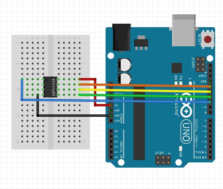
-
Flash the bootloader! This will set the ATtiny85 to the clock speed you selected. Go to Tools->Burn Bootloader (make sure ATtiny85 is the target board, and you have "Arduino as ISP" as your programmer). If you get an ERROR, either:
- you're not powering the ATtiny85 correctly
- you have incorrect wiring or a broken cable
- you don't have "Tools/Programmer/Arduino as ISP" selected as your programmer (not "ArduinoISP")
- you don't have the "File/Examples/ArduinoISP" sketch uploaded to your Arduino Uno
- you don't have the ATtiny85 selected as your target board
- you accidentally broke you ATtiny85 or the Arduino Uno. Try another, and if it still errors, see reasons above.
-
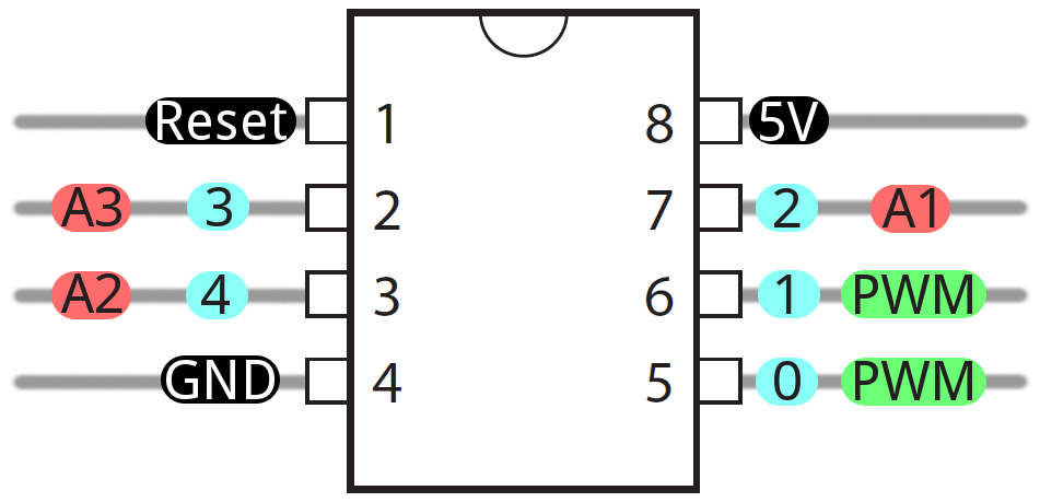
Make something :) Here is a link to ATtiny85 pin description (Arduino pins are labelled blue in the picture), and also other hardware descriptions for connecting to different sensors and outputs.
[FYI] ATmega328p on a Breadboard
-
Arduino's tutorial on bootloading an ATmega328p on a breadboard using an Arduino Uno as the programmer
-
Arduino's tutorial on making a breadboard Arduino, which includes the supporting power, timing, and communications circuitry.
Wireless Modules
Design #2
Below are some wireless modules to use with you DIY boards. They are good choices at this time because they use wireless protocols that are useful to most ITP projects, they are available for low-quantity purchase in the U.S., and they have Arduino support.
RFm69HW - (915 or 433 mHz)
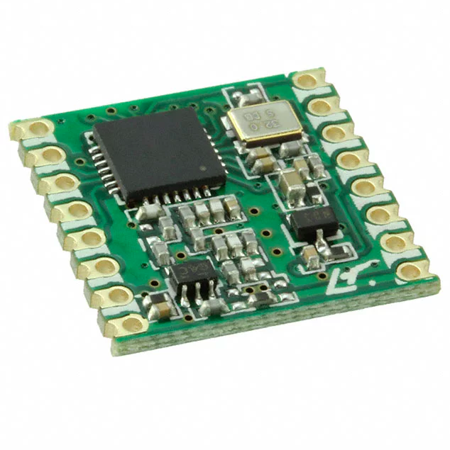
The RFm69 is a simple radio module, great for mesh networking. This means your Arduino projects can communicated directly to each other in any configuration (one-one, one-many, many-one).
-
Pros:
- Mesh networking made simple
- Connects to ATmega328, so you can run your normal Arduino Uno code
- Low power options to save battery life
-
Cons:
- More parts needed, because it requires ATmega328 or similar IC
- Cannot directly connect with phones and other computers
- Long antenna, which you have to cut yourself from a wire
- Source:
- Documentation:
esp8266
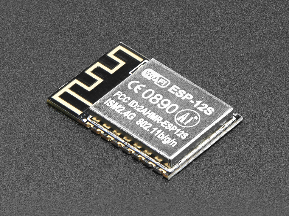
The esp8266 is a very cheap WiFi IC that can also run Arduino code, and it comes in several breakout boards, modules, and prototyping boards.
-
Pros:
- Very low cost
- Runs Arduino code, and uses the Arduino WiFi library
-
Cons:
- Only 1 analogRead pin, and all pins use software PWM
- Source:
- Documentation:
esp32
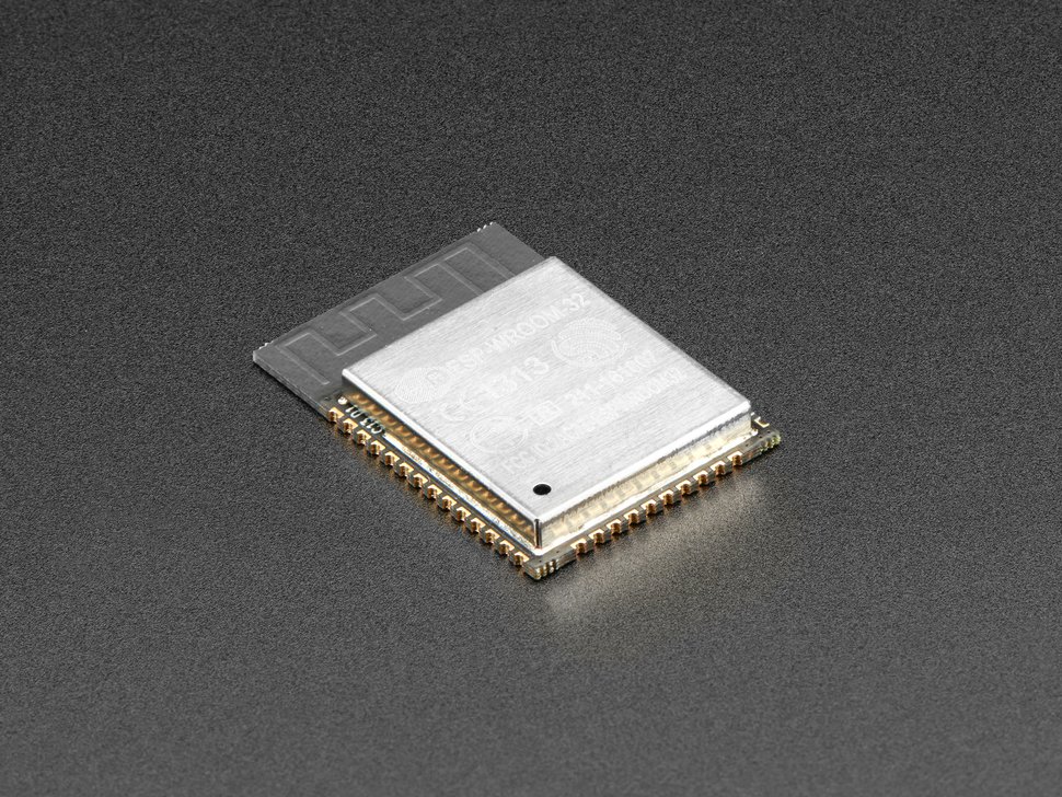
The esp32 and new update over the esp8266. Like the older one, it can do WiFi, and can advertise over BLE. However it's much newer, so as of now (Spring '18) it doesn't have all Arduino functions, like analogWrite for example.
-
Pros:
- Low cost
- Runs Arduino code, and uses the Arduino WiFi library
- Can advertise as a BLE peripheral (no GATT support yet)
- Has WAY more pins than the esp8266, inluding capacitive-touch inputs
-
Cons:
- Firmware (Arduino support) is not fully implemented because it's so new
- Source:
- Documentation:
RFduino
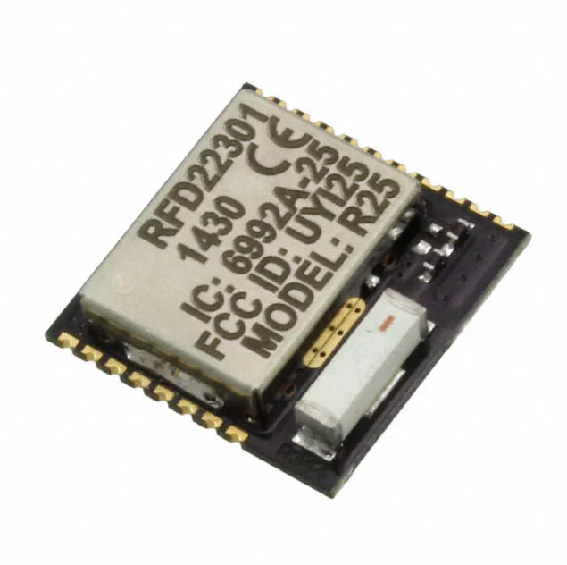
The nRF51 is can run Arduino code, and communicate over Bluetooth Low Energy (BLE). It also comes in many modules and breakouts, but is most available to us in New York as the RFduino module.
-
Pros:
- Has BLE GATT/GAP support
- Hardware PWM and analogRead on all pins
- Runs Arduino code and BLE stack on same chip
-
Cons:
- The RFduino is on the expensive end for modules
- Source:
- Documentation:
nRF52
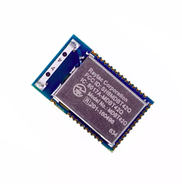
The nRF52 is the newer BLE IC from nordic (older version is nRF51). The module we use (from Raytac/Seeed) is smaller so it's harder to solder, but the IC is a great improvement over the older nRF51.
-
Pros:
- Same pros as nRF51 listed above ^^^
- The module is new, but there is much better Arduino support and more to come!
-
Cons:
- Harder to solder down that other module because the pins are small
- Requires a J-Link in order to flash the bootloader
- Source:
- Documentation:
Eagle Schematic
Design #3
Here's a thorough list of Eagle Commands from MIT's course on Eagle.
Adding Parts
The Adafruit Eagle library and the Sparkfun Eagle libraries have a ton of parts for you to use.
Here is a very helpful search tool created by Dangerous Prototypes. You enter a part number you need, and it searches GitHub for any Eagle files that contain that part, so you can simply copy/paste into your design.
Making a Schematic
Sparkfun tutorial on Eagle's schematic view.
Video from Class #2:
Eagle Board View
Design #4
A simple list of the Eagle commands, for quick reference.
Turning a Schematic in to a Board View
Sparkfun tutorial on Eagle's board view, stop when you get to "Routing the Board".
Eagle Routing
Design #5
A simple list of the Eagle commands, for quick reference.
Drawing Routes
Start at "Routing the Board" in the Sparkfun tutorial on Eagle's board view, stop when you get to "Generating Gerbers".
Adding Ground-Plane in Eagle
A "ground-plane" is when, instead of ROUTE'ing your GND connections, you can draw a POLYGON that fills in the entire PCB with your GND signal. Ground-planes help shielding noise, cooling your circuit, and often times making production a little simpler.
The steps to draw a ground plane in your Eagle board file:
- Select the POLYGON tool in your Eagle board view
- Set your grid to something not too small, I like 1mm. This is important because to complete a POLYGON, the final line must finish at the exact same point as the first line began.
- Draw your POLYGON around your entire PCB, following the DIMENSION lines if you have already drawn those.
- Finish by completing the shape (click the first line), and the POLYGON will turn into a dotted-line
- Select the NAME tool, and name the POLYGON "GND" so it is "connected" to your GND signals.
- To fill in your ground plane, enter the command RATSNEST. This will fill all possible ground signals with a plane of copper.
- Check to make sure that all GND pads/pins are touching the ground-plane. If a pad/pin is isolated from the other grounds, then you will either need to re-route, or use VIAs to have all GND pads/pins touching the ground-plane.
Using the OtherMill
Production #1
- Maintenance and making sure ITP's mills don't break
- Hello World: milling a simple PCB
1 - Load design and bits
Drag and drop your Eagle .brd file into Otherplan, and your design will appear in 3d model and as a new entry on the right side. Add all the bits you will be using for this board (aka 1/32", 1/16")
2 - Inspect and adjust Eagle file
With the correct bits selected, carefully look over your design and check to see if any traces are too close, or any holes are too small they won't be drilled. (link to Bantam Tool's Design Considerations)
To fix any problems, keep Otherplan open, and also open the Eagle file to edit. Adjust your traces, or drop new holes, and press SAVE in Eagle. You can then press the refresh key on your file in Otherplan, and the changes will appear.
3 - Connect to Othermill
Once your file is ready to be milled, you can start using the machine.
Power the Othermill on, and connect to your laptop over the USB cable. Otherplan should now say that you are connected to a mill, and can control it.
4 - Optional: Attach Bracket and Locate
This is only needed if you are doing a double-sided PCB. Read Bantam Tool's guide for how to probe the bracket.
5 - Prepare copper plate
The Othermill is designed to hold plates 5"x4". If your board is larger than this, you can cut it to size in the shop.
Apply double-sided tape to the bottom of your board, and press if firmly down onto the Othermill's bed. Press firmly and for about 30 seconds, making sure that the tape fully stuck and flat to the aluminum bed.
6 - Change Tool and Locate
The top-right of Otherplan will show what bit it thinks is currently connected. This might not be a bit your using, or could just be completely wrong, the machine's not that smart.
Select Change Tool, and follow the instructions. You should add the smallest bit your job is using (aka 1/32"), and follow the instructions for locating. The bits must be located every time after they're inserted.
7 - [New Feature] PCB Probe
This is great. If you have the PCB Probing System, then the machine can measure the thickness of your board for you. Read Bantam's guide for how to use it.
Simply though, with the PCB probe touching your copper plate, go to Menu_Bar->BitBreaker->Probe_Material_Thickess.
If your bit doesn't cut through the copper while cutting, it means some spots on your plate are thinner than others. When this happens, cancel your job, and got up to the Material box in the software and open the Size section. Lower the thickness by 0.05-0.1mm, so if mine was 1.52mm before, I'll change it to 1.50 or even 1.47. Press ENTER so the value is saved, then try milling again.
8 - Run Job
Once correct bit is setup, and your material is ok, you can press "Start Cutting!". While the job is running, do not listen to headphones, and do not leave the machine alone.
If your job is using multiple bits, the machine will automatically stop and ask you to change bits. Follow the instructions just like before, and it will continue with the job.
9 - Remove and clean
Once the job is finished, use a vacuum to clean both your board and the entire insides of the Othermill (including those hard-to-reach places in the top).
Scrub your board with a scour pad to remove any roughness and copper hairs, and test all connections with a multimeter
Toner Transfer
Production #2
1 - Make the printout
Hide all layers in your Eagle .brd file, and only show the layers that you want to remain after acid etching. These usually include Top (or Bottom), Pads, Vias, and Dimension.
When only those are visible, File->Print and save as a PDF file. Make sure you have the "Solid" and "Black" options checked. If you are etching onto the Top of your board, also select "Mirror" and your design will flip horizontally. If you are etching onto the Bottom of your board, leave it unselected.
Use Illustrator or similar software to place your design on the sheet, or to make multiple copies of your design for one sheet. Print your design onto transfer paper using the laser printer in the hard-lab. If using the blue transfer paper, make sure you are printing onto the glossy side of the sheet.
2 - Heat with Laminate and Iron
Before applying ink to your copper plate, make sure your board is shiny and clean. Scrub off any dirt with a scour pad, and then clean it with isopropyl rubbing alcohol and dry off.
Place your printed design face-down onto your copper place and align with any holes you might have already drilled. Once aligned, add a small piece of tape to one side of the paper so that it doesn't shift in the laminator.
Heat the laminator up to it's 5-mil setting. This takes about 5 minutes, so start heating it up early. Firmly hold your paper to the board so it doesn't move, and slowly feed it through the laminator. Do this 5-10 times (sometimes longer!)
Once the transfer paper/vinyl is firmware stuck to the copper pad, you can stop laminating it and move on to a clothes iron. Put the iron on HIGH heat setting, and heat your toner paper/vinyl for 1-3 minutes under the iron. If you are heating a larger PCB that doesn't entirely fit under the iron, do an additional 1-3 minutes for each section of your PCB.
3 - Water and remove paper
When done laminating, place the board and paper still stuck together in a tupperware container with cold water in it. Leave for a couple minutes, or until the transfer paper floats away from the copper plate. Peel back the paper, and your traces should be written in black ink on your copper plate.
What happened is you heated copper plate and ink so that it melts onto the copper. Not hot enough, and only part of your design will transfer to the copper. Too hot, and the ink will start to bubble on the copper. If you don't heat it for the right amount of time and the transfer doesn't work, simply rub off the ink with a scour pad, and start again.
4 - Air-dry and fix with sharpie
Do not touch the toner, as it is still soft can move around. To dry the board off, use a hair dryer from the shop, and try not to let anything touch your design.
If there are any spots on your design missing some ink, you can simply use a permanent black marker to correct the mistake. You could even skip the entire toner transfer process, and simply draw onto a copper plate with permanent marker!
Acid Etching
Production #2
Just watch the first half of this video...
1 - Prepare board
As mentioned in the toner transfer section, you can fix any mistakes in your design with a permanent maker. Apply the marker to a dry plate, and try to spread the ink thick so it fully covers the copper.
2 - Prepare acid
If you are using [muriatic acid + hydrogen peroxide], measure them at a 1-2 ratio (aka 1/4 cup of muriatic acid, and 1/2 cup of hydrogen peroxide), and make sure to first add the hydrogen peroxide, then second add the muriatic acid to your tupperware container. It should be a clear color before you etch.
If you are using ferric chloride, simply pour from the gallon container of pre-mixed acid into your tupperware container. It should be brown before you etch.
3 - Etch and Shake
With a second container of water next to it and wearing rubber gloves, add your copper plate to the acid. Mix the acid constantly by gently lifting one side, causing a wave pattern to move back and forth. With a rubber glove on, you can remove and inspect the plates. Once they are etching, they will start turning pink or purple.
Eventually all your visible copper will disappear. How long this takes depends on the intensity of the acid. The muriatic acid mixture can be very fast right after mixing, and will eventually turn green/blue as it absorbs the copper. The ferric chloride can take more time, and will start turning green as it absorbs copper.
4 - Clean up and finish
When your board is finished etching, remove it from the acid and put it in your water container. Pour your used acid into one of the "old acid" buckets. That stuff is now filled with copper, and is bad for the environment and cannot simply be thrown away.
Rinse out your tupperware containers and board in the slop sink, making sure to rinse away any tiny amounts of acid that might be in the sink. Dry your board with a hair dryer, then remove the black ink with a scour pad.
Engraving Bit Isolation Milling
Production #2
Bantam Tool's has the feature of using an 30 degreen engraving bit to millout the a circuits traces. This is an amazing new feature that allows us to mill much much smaller traces and component pads.
Here's a link to their tutorial on using the new feature.
Cleaning a Milled Copper Plate
Production #3
[WARNING] The below video is old, and we now can mill double sided boards on the same plate. However, the same rules apply when cleaning it.
Laser Etch a Solder Stencil
Production #3
1 - Make the printout
A solder stencil is a sheet of material with holes cut out of it. These holes represent the parts of your design that solder paste should be on, and is assigned the Eagle layers tCream and bCream. If I'm making a stencil for the top of my board, I'll hide all layers except the tCream layer, then I'll save as a PDF. Make sure to select the "black" and "solid" options.
The size of each hole needs to be shrunk by about 70% before we make the stencil. To do this is Illustrator, open the PDF, and select each shape in the design. Navigate to Object->Transform->Transform Each..., and a popup will appear. Scale the width and height of each shape by 70% each, and apply the changes. Now each hole should be smaller.
2 - Raster stencil
Inser a piece of transparency film into one of the Epilog laser cutters. Load your PDF file, and go into the Print options. Using the Epilog's driver, set the laser cutter's Job Type to "Raster," and set the rastering speed and power to low settings. On the 60 watt machine, speed=10 and power=10 work well, while on the 50 watt it seems speed=10 and power=15 works well.
Send the job to the laser cutter, and run it. The laser cutter will slowly cut out your stencil line by line. If it doesn't cut through the material, the power should be set higher. If the edges of the holes are not clean and seem melted, the power should be set lower.
3 - Align and tape
Cut out your stencil, and align it with your PCB. If PCB is still attached to the larger copper plate, you can tape down the top of the stencil to the plate. If your PCB is fully cut out right now, squeeze your PCB between three other plates, one at the top, two at each side, and tape the stencil to the plate at the top. This helps keep the stencil flat when applying paste.
4 - Spread paste
Place a small line of solder paste along the top of you design so that it is the same width. Using a flat scraping tool like an old ID or credit card, firmly press and pull the paste over the entire stencil in one motion. This should press the paste through each hole in the stencil.
Pull up the stencil and check your board to see that the sold spread correctly. If it didn't go well, you can simply clean the paste off and try again. When you are done with the stencil, be sure to scape off all un-used solder paste and put it back in the tub to be reused.
5 - Adjust with needle
If small changes need to be made, either removing or adding paste, you can use a sewing needle to adjust and move solder paste around. You could even apply paste to an entire board just using a needle, no stencil needed, but this takes a bit longer and is of less quality.
Tutorials on Soldering
Production #4
[WARNING] The below videos are old, and we now can mill double sided boards on the same plate. However, the same rules apply when soldering.
Sparkfun's Tutorials on SMD Soldering
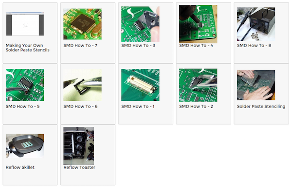
Sparkfun's tutorials are focused on how to solder the parts down, whether using an iron, hot air gun, skillet, or toaster oven.
Populate with the SMT Station
Production #4
1 - Power on
The SMT Station has a large red switch along the right side, which will brighten up when turned on. The compresser as a red switch on its top, and when turned on will immediately begin filling the SMT Station with compressed air. Nothing else is needed to be done, because the compressor will automatically turn on and off when more air is needed.
2 - Place board
The the magnetic wedges to hold your PCB, and rest your forearm on the black arm rest. A light should be placed above the workspace to help visibility.
3 - Prepare parts
The SMT station can hold a wide array of parts, but you are likely to be using parts not found there. Before beginning your job, make sure that all components you need are present and able to be used. If you find that a compartment in the SMT Station needs to be refilled, please take initiative and fill it up.
4 - Pick and place
When you press down on a part with the nozzle, the station will turn on its suction to pickup the part. When you press down again, the suction will turn off. The nozzle will also rotate along with the rotary knob you use to guide the nozzle around.
If you place a part wrong and have to redo it, I suggest fixing the part with a pair of tweezers. The solder paste on your board will be holding your part down, and the SMT Station is often times not strong enought to re-pick it up.
5 - Power down
Once finished placing your parts, put the nozzle in a safe position. Power down the SMT Station with the red power switch, and turn the compressor off with it's red switch. Clean up any parts, reel tape, or solder that is on the machine.
Reflow with the Heat Gun
Production #4
1 - Warm the board
A few minutes before reflowing your board, you should heat up the heat pad so that it is fully hot. Place your PCB with solder paste and components on the heat pad, and let is warm for a 1-2 minutes. This will soften the paste for better reflow.
2 - Set to around 240 degrees
Turn the heat gun on by setting both switches to ON, and set the temperature to 240 celsius. Solder paste melts around 200-240 degrees celsius, depending on the solder your using.
3 - Reflow
Carefully hold the heat gun facing down above your PCB, and slowly move it around about 1-2 cm above your board. After about 30 seconds, your solder paste will heat to the point of melting, and will turn a bright and shiny silver. Once all of your paste is shiny silver, heat for another 5 seconds, then put the gun away and power it OFF.
4 - Inspect and re-reflow
Inspect your solder joints for any bridges, tombstones, or incomplete connections. You can use the magnifying glass to get the best view of your board. If a part needs adjusting, you can re-heat the part with the heat gun, and while still heating it, adjust the with tweezers.
Adafruit Tutorials on SMD Manufacturing
Production #4
Adafruit has a great set of tutorials for handling SMD parts, but they're aimed at manufacturers rather than prototypers. Also we do things a little differently here, but still worth a read for if you end up doing small-scale manufacturing in the future.
Programming Jigs
Production #5
- Here's a tutorial on making a "real" programming jig. This is too professional for what we'll be doing in class, but you can imagine how much design goes into just thinking about how something will be programmed.
- Here's an example of someone hot-gluing some wire to program a dead Pro Mini. That's a jig too.
Bootloaders
Production #5
A Bootloader is a small piece of code that we usually need to put on our microcontrollers before we can program them with Arduino. Any board that works with the Arduino IDE has an "Arduino" bootloader inside it, giving it the ability to load code from the Arduino IDE.
Here's an explanation of what the Arduino Bootloader is from Sparkfun.
Whenever code is transfered from a computer to a microcontroller, something must be in the middle acting as a converter. This is a usb-to-serial converter, or a usb-to-spi converter, or something similar. These middle devices are call In-System Programmers (ISP).
Here's a tutorial on using Arduino as an ISP (In System Programmer)
Here's an example of adding a bootloader to an nRF51822, so that we can program it with Arduino. Unlike Atmel chips which use the mkii as an ISP, the nRF5x chips use the J-Link as an ISP.