[2017 archive] Homemade Hardware
Steps to Making a PCB
Design
-
Prototype
-
Bill of Materials
-
Schematic
-
Layout & Shape
-
Design Copper
Production
-
Cutout & Holes
-
Remove Copper
-
Board Finishing
-
Populate & Reflow
-
Programming
Physical Computing
Design #1
The Physical Computing website is packed with everything you'll need to know about electronics and programming for this class. Specifically, the following pages should be reviewed:
Topics
Labs
Electricity
Design #1
We'll be going over the basics in class, but electricity is weird, so branch out and let it sink in.
-
CircuitJS is a cool simulator to interact with circuits and see how they work.
-
Logic levels, or how to communicate with voltage, as explained by Sparkfun.
-
Also Sparkfun explains Analog v.s. Digital electrical signals.
Microcontrollers
Design #2
We'll be sticking with Arduino-compatible chipsets in this class so we don't have to leave the Arduino IDE. However, when making your own boards, it helps to have a grasp of what's happenning at lower levels.
Under the hood
-
Sparkfun's explaination of what an Integrated Circuit (IC) is.
-
Arduino's explaination of what happens when you hit Upload.
Arduino on a breadboard
-
Here is the Board file for the ATmega328p Internal 8mhz (meaning no crystal needed)
-
Arduino's tutorial on bootloading an ATmega328p on a breadboard using an Arduino Uno as the programmer
-
Arduino's tutorial on making a breadboard Arduino, which includes the supporting power, timing, and communications circuitry.
-
Tutorial on programming an ATtiny85, using an Arduino Uno.
Arduino Board Manager
-
Here's an overview from Adafruit on using the Board Manager to install third-party boards. This tutorial tells you to download Adafruit's boards, but can be applied to all other boards.
-
Here is a list of all third-party boards supported by Arduino. Simple use the URL's from this page (they end in a .json) and paste them into the Preferences input, as explained in the tutorial above.
Wireless Modules
Design #2
Below are three wireless modules to use with you DIY boards. They are good choices at this time because they use wireless protocols that are useful to most ITP projects, they are available for low-quantity purchase in the U.S., and they have Arduino support.
RFm69HW - (915 or 433 mHz)
The RFm69 is a simple radio module, great for mesh networking. This means your Arduino projects can communicated directly to each other in any configuration (one-one, one-many, many-one).
-
Pros:
- Mesh networking made simple
- Connects to ATmega328, so you can run your normal Arduino Uno code
- Low power options to save battery life
- Long range (longer if 433mhz)
-
Cons:
- More parts needed, because it requires ATmega328 or similar IC
- Cannot directly connect with phones and other computers
- Longer antenna that you have to make
- Source:
- Documentation:
esp8266
The esp8266 is a very cheap WiFi IC that can also run Arduino code, and it comes in several breakout boards, modules, and prototyping boards.
-
Pros:
- Very low cost
- Runs Arduino code, and uses the Arduino WiFi library
-
Cons:
- Must have access to the local WiFi network's name and password
- WiFi requires more power, so this will kill batteries
- WiFi connection and communication latency can be large (slow)
- Only 1 analogRead pin, and all pins can use software PWM
- Source:
- Documentation:
nRF51822 (RFduino)
The nRF51822 is a powerful IC that can run Arduino code, and communicate over Bluetooth Low Energy (BLE). It also comes in many modules and breakouts, but is most available to us in New York as the RFduino module.
-
Pros:
- Hardware PWM and analogRead on all pins
- Runs Arduino code and BLE stack on same chip
- Capable of very low-power use
- Connects to computers and phones directly, without any pairing or passwords
-
Cons:
- More expensive than other modules
- Source:
- Documentation:
Eagle Schematic
Design #3
A simple list of the Eagle commands, for quick reference. And here's a more thorough one from MIT's course on Eagle.
Adding Parts
The Adafruit Eagle library and the Sparkfun Eagle libraries have a ton of parts for you to use.
Here is a very helpful search tool created by Dangerous Prototypes. You enter a part number you need, and it searches GitHub for any Eagle files that contain that part, so you can simply copy/paste into your design.
Making a Schematic
Sparkfun tutorial on Eagle's schematic view.
Eagle Board View
Design #4
A simple list of the Eagle commands, for quick reference.
Turning a Schematic in to a Board View
Sparkfun tutorial on Eagle's board view, stop when you get to "Routing the Board".
Eagle Routing
Design #5
A simple list of the Eagle commands, for quick reference.
Drawing Routes
Start at "Routing the Board" in the Sparkfun tutorial on Eagle's board view, stop when you get to "Generating Gerbers".
Using the OtherMill
Production #1
- Maintenance and making sure ITP's mills don't break right when you want to use them
- Hello World: milling a simple PCB
- Otherduino: milling the Othermill's Arduino clone
1 - Setup material in Otherplan
Select the copper plate you will be using, and measure it's width and height with a ruler. Then [IMPORTANT] measure it's thickness with calipers.
In the top right corner of Otherplan, you can Setup Material. Select double-sided FR-1, and enter the dimensions you measured earlier.
2 - Load design and bits
Drag and drop your Eagle .brd file into Otherplan, and your design will appear in 3d model and as a new entry on the right side. Add all the bits you will be using for this board (aka 1/32", 1/16")
3 - Inspect and adjust Eagle file
With the correct bits selected, carefully look over your design and check to see if any traces are too close, or any holes are too small they won't be drilled
To fix any problems, keep Otherplan open, and also open the Eagle file to edit. Adjust your traces, or drop new holes, and press SAVE in Eagle. You can then press the refresh key on your file in Otherplan, and the changes will appear.
4 - Connect to Othermill
Once your file is ready to be milled, you can start using the machine.
Power the Othermill on, and connect to your laptop over the USB cable. Otherplan should now say that you are connected to a mill, and can control it.
5 - Prepare copper plate
The Othermill is designed to hold plates 5"x4". If your board is larger than this, you can cut it to size in the shop.
Apply double-sided tape to the bottom of your board, and press if firmly down onto the Othermill's bed. Press firmly and for about 30 seconds, making sure that the tape fully stuck and flat to the aluminum bed.
6 - Change Tool and home
The top-right of Otherplan will show what bit it thinks is currently connected. This might not be a bit your using, or could just be completely wrong, the machine's not that smart.
Select Change Tool, and follow the instructions. You should add the smallest bit your job is using (aka 1/32"), and follow the instructions for homing. The Z-axis must be homed every time after a new bit is inserted.
7 - Run Job
Once correct bit is setup, and your material is ok, you can press "Start Cutting!". While the job is running, do not listen to headphones, and do not leave the machine alone.
If your job is using multiple bits, the machine will automatically stop and ask you to change bits. Follow the instructions just like before, and it will continue with the job.
8 - Remove and clean
Once the job is finished, use a vacuum to clean both your board and the entire insides of the Othermill (including those hard-to-reach places in the top).
Scrub your board with a scour pad to remove any roughness and copper hairs, and test all connections with a multimeter
Using the Rolend Modela
Production #1
Using the Roland Modela and Nodela interface:
1 - Tape down the copper palte
Apply double-sided tape to the bottom side of your copper plate. Place it it on the bed, and firmly press down. While pushing down, slide your hand along the plate to make sure all the tape is pressed flat.
2 - Using the machine
Press the top green button on the mill, and it will power on and home. There is a green LED next to the white button labelled VIEW. If the light is on, then VIEW is on, and the machine will ignore all messages sent to it. When VIEW is off, the machine will listen to messages and move around. You can use the VIEW button to pause and later resume a job.
When VIEW is off, you can use the UP and DOWN buttons to move the head along the Z axis. Single button presses will move the head one micron (1/1000 inch). Keep holding the button down, and the mill will move continuously until you release the button.
3 - Start the interface
The serial cable being used at ITP requires a driver to be installed on the laptop. You can find a driver here.
Download the software from the github repository, the readme describes how to install. Open and run, and connect the mill's USB cable to your computer. Press the SCAN PORTS button to find the mill's serial port. Select the correct port, and press CONNECT.
Drag your Eagle .brd file onto the interface, and your design will load. Buttons will generate for the layers in your file. When a layer is selected, it's contents will turn red in the graphic, indicating which toolpaths will be sent to the mill.
4 - Add and home a bit
The machine will think that whatever height you set it the Z axis to is the top of your copper plate, so we have to touch our plate with the bit before running a job.
With the Z axis all the way up, slide your first bit into the collet, and tighten both the two hex screws.
With the Z axis still all the way up, use the arrows on the interface to move the bit along the X and Y axis until it's over the copper. Move the Z axis down until the tip of the bit touches the copper, even making a tiny mark on the surface.
5 - Enter layer, but, and cut depth
Select the first Eagle layer you want to mill by pressing it's button on the interface. Select from the menu what sized bit you will use. The bit you select will change the speed and plunge depth of the machine.
Then enter the depth you would like it to cut down to (in inches). If just removing copper for traces, set a small depth (like 0.01). If drilling holes or cutting dimension, enter the total thickness of your board (measure with calipers).
6 - Running a job
Double check your bit is touching the copper plate, and has an X and Y position that will fit your design. Press RUN JOB, and the selected layer will begin cutting. When the job is finished, the bit will move back to origin.
To pause a job will it's running, press the VIEW button. To resume the job, press the VIEW button again and the machine will start up immediately.
7 - Erasing a job
The job is being slowly fed from your laptop to the machine, so we have to first erase it in the mill, then we erase it in your laptop by quiting the interface.
To erase a job, first pause it by pressing the VIEW button. While in VIEW mode, press the UP and DOWN buttons at the same time, and the light will start flashing. Shut down the interface, and then the light will stop flashing. You have fully erased the job, and can now restart the interface.
Toner Transfer
Production #2
1 - Make the printout
Hide all layers in your Eagle .brd file, and only show the layers that you want to remain after acid etching. These usually include Top (or Bottom), Pads, Vias, and Dimension.
When only those are visible, File->Print and save as a PDF file. Make sure you have the "Solid" and "Black" options checked. If you are etching onto the Top of your board, also select "Mirror" and your design will flip horizontally. If you are etching onto the Bottom of your board, leave it unselected.
Use Illustrator or similar software to place your design on the sheet, or to make multiple copies of your design for one sheet. Print your design onto transfer paper using the laser printer in the hard-lab. If using the blue transfer paper, make sure you are printing onto the glossy side of the sheet.
2 - Laminate
Before applying ink to your copper plate, make sure your board is shiny and clean. Scrub off any dirt with a scour pad, and then clean it with isopropyl rubbing alcohol and dry off.
Place your printed design face-down onto your copper place and align with any holes you might have already drilled. Once aligned, add a small piece of tape to one side of the paper so that it doesn't shift in the laminator.
Heat the laminator up to it's 5-mil setting. This takes about 5 minutes, so start heating it up early. Firmly hold your paper to the board so it doesn't move, and slowly feed it through the laminator. Do this 5-10 times (sometimes longer!)
3 - Water and remove paper
When done laminating, place the board and paper still stuck together in a tupperware container with cold water in it. Leave for a couple minutes, or until the transfer paper floats away from the copper plate. Peel back the paper, and your traces should be written in black ink on your copper plate.
What happened is you heated copper plate and ink so that it melts onto the copper. Not hot enough, and only part of your design will transfer to the copper. Too hot, and the ink will start to bubble on the copper. If you don't heat it for the right amount of time and the transfer doesn't work, simply rub off the ink with a scour pad, and start again.
4 - Air-dry and fix with sharpie
Do not touch the toner, as it is still soft can move around. To dry the board off, use a hair dryer from the shop, and try not to let anything touch your design.
If there are any spots on your design missing some ink, you can simply use a permanent black marker to correct the mistake. You could even skip the entire toner transfer process, and simply draw onto a copper plate with permanent marker!
Acid Etching
Production #2
Just watch the first half of this video...
1 - Prepare board
As mentioned in the toner transfer section, you can fix any mistakes in your design with a permanent maker. Apply the marker to a dry plate, and try to spread the ink thick so it fully covers the copper.
2 - Prepare acid
If you are using [muriatic acid + hydrogen peroxide], measure them at a 1-2 ratio (aka 1/4 cup of muriatic acid, and 1/2 cup of hydrogen peroxide), and make sure to first add the hydrogen peroxide, then second add the muriatic acid to your tupperware container. It should be a clear color before you etch.
If you are using ferric chloride, simply pour from the gallon container of pre-mixed acid into your tupperware container. It should be brown before you etch.
3 - Etch and Shake
With a second container of water next to it and wearing rubber gloves, add your copper plate to the acid. Mix the acid constantly by gently lifting one side, causing a wave pattern to move back and forth. With a rubber glove on, you can remove and inspect the plates. Once they are etching, they will start turning pink or purple.
Eventually all your visible copper will disappear. How long this takes depends on the intensity of the acid. The muriatic acid mixture can be very fast right after mixing, and will eventually turn green/blue as it absorbs the copper. The ferric chloride can take more time, and will start turning green as it absorbs copper.
4 - Clean up and finish
When your board is finished etching, remove it from the acid and put it in your water container. Pour your used acid into one of the "old acid" buckets. That stuff is now filled with copper, and is bad for the environment and cannot simply be thrown away.
Rinse out your tupperware containers and board in the slop sink, making sure to rinse away any tiny amounts of acid that might be in the sink. Dry your board with a hair dryer, then remove the black ink with a scour pad.
Engraving Bit Isolation Milling
Production #2
OtherMill's new software has the feature of using an engraving bit to millout the a circuits traces. This is an amazing new feature I'm going to try once the new OtherMill's come to ITP
Here's a link to their tutorial on using the new feature.
Cleaning a Milled Copper Plate
Production #3
[WARNING] The below video is old, and we now can mill double sided boards on the same plate. However, the same rules apply when cleaning it.
Dry-Film Solder Mask
Production #3
Great video on using the dry-film solder mask, step-by-step.
1 - Design the printout
Our solder mask will cover everything except the places where we need to solder something. Those spots have their own layers in Eagle, call ehd tStop and bStop layers. If I'm making a mask for the top of my board, then I'll hide every layer except the tStop layer, and save as a PDF. Make sure you have the "black" and "solid" options checked.
You can then further design your tStop printout by opening the PDF in software like Illustrator. You can place the ink anywhere on the paper, and copy and paste the design to make multiple copies.
2 - Print on transparency paper
ITP uses laser printers, and most transparency papers will melt and destroy a laser printer. You need to make sure you are using transparency paper specifically designed to go through a laser printer!.
Use this transparency paper to print your tStop layer in black ink. If any spots come out too thin, you can thicken the ink with a permanent marker.
3 - Clean and test board
Before adding a solder mask to you board, you'll want to make sure all your traces and holes are correct and not bridging. Scrub with a scour pad, and use a multimeter to beep-test all connections. Once the solder mask is added, this sill be more difficult to test.
4 - Laminate film
Cut out a piece of green dry-film solder mask large enough to cover your copper traces. The film as two sides, one shiny and smooth, the other duller and matte. Peel off the plastic on the dull/matte side to expose the adhesive. Press the film ontop of your copper traces, and rub all over to remove any air bubbles.
Pass your copper plate through the heated up laminator, with the film stuck stuck on. The laminator melts the adhesive on the film, letting it stick better to the copper plate. After about 4 passes through, quickly run your board under cold water to quickly cool the adhesive and strengthen the bond.
5 - Align and expose to UV
Take your transparency with the black tStop or bStop layer, and align it to your board. Place in the UV exposure unit, and make sure the transparency stays aligned. Expose the board to UV light to cure all the solder-mask that's not under black ink.
The amount of time it takes for this exposure step depends on the intensity of the UV expsosure unit. UV exposure units must be tested to find their best value, and given a label to indicate times.
6 - Leave in dark for 30 minutes
After exposing to UV light, leave your board in a dark place for about 30-60 minutes. It has been said that this is an important step in creating the best results.
7 - Develop
Fill a tupperware container with warm/hot water, and add 1/2 a spoon full of sodium carbonate (a white powder). Add your plate to the container. Using a toothbrush or similar, gently rub your boad to help the developer.
After a few seconds, you should start to see your tStop or bStop layers revealed through the dissolving solder mask. Continue developing and gently brushing for another minute or so until the copper pads are fully revealed. Do not develop for too long, however, or you will remove more solder mask than you want to.
When done, remove from the developer, clean under a water faucet, and dry with a hair dryer. Do not touch the solder mask, as it is still soft and can fall off.
8 - Cure under UV
To fully cure the solder mask, put it back under UV light for 5-20 minutes. This will make your solder mask dry and crispy. Aftewards, solder mask can be removed by simply scrapping at it with a sharp tool to expose the copper underneath.
Laser Etch a Solder Stencil
Production #3
1 - Make the printout
A solder stencil is a sheet of material with holes cut out of it. These holes represent the parts of your design that solder paste should be on, and is assigned the Eagle layers tCream and bCream. If I'm making a stencil for the top of my board, I'll hide all layers except the tCream layer, then I'll save as a PDF. Make sure to select the "black" and "solid" options.
The size of each hole needs to be shrunk by about 70% before we make the stencil. To do this is Illustrator, open the PDF, and select each shape in the design. Navigate to Object->Transform->Transform Each..., and a popup will appear. Scale the width and height of each shape by 70% each, and apply the changes. Now each hole should be smaller.
2 - Raster stencil
Inser a piece of transparency film into one of the Epilog laser cutters. Load your PDF file, and go into the Print options. Using the Epilog's driver, set the laser cutter's Job Type to "Raster," and set the rastering speed and power to low settings. On the 60 watt machine, speed=10 and power=10 work well, while on the 50 watt it seems speed=10 and power=15 works well.
Send the job to the laser cutter, and run it. The laser cutter will slowly cut out your stencil line by line. If it doesn't cut through the material, the power should be set higher. If the edges of the holes are not clean and seem melted, the power should be set lower.
3 - Align and tape
Cut out your stencil, and align it with your PCB. If PCB is still attached to the larger copper plate, you can tape down the top of the stencil to the plate. If your PCB is fully cut out right now, squeeze your PCB between three other plates, one at the top, two at each side, and tape the stencil to the plate at the top. This helps keep the stencil flat when applying paste.
4 - Spread paste
Place a small line of solder paste along the top of you design so that it is the same width. Using a flat scraping tool like an old ID or credit card, firmly press and pull the paste over the entire stencil in one motion. This should press the paste through each hole in the stencil.
Pull up the stencil and check your board to see that the sold spread correctly. If it didn't go well, you can simply clean the paste off and try again. When you are done with the stencil, be sure to scape off all un-used solder paste and put it back in the tub to be reused.
5 - Adjust with needle
If small changes need to be made, either removing or adding paste, you can use a sewing needle to adjust and move solder paste around. You could even apply paste to an entire board just using a needle, no stencil needed, but this takes a bit longer and is of less quality.
Milling a Solder Stencil on OtherMill
Production #3
Here is the link using the OtherMill to mill a stencil for solder paste. I haven't tried this yet, but Kina Smith had success a couple years ago.
Tutorials on Soldering
Production #4
[WARNING] The below videos are old, and we now can mill double sided boards on the same plate. However, the same rules apply when soldering.
Sparkfun's Tutorials on SMD Soldering
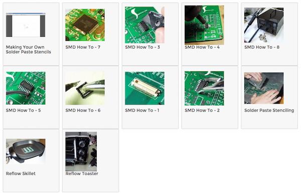
Sparkfun's tutorials are focused on how to solder the parts down, whether using an iron, hot air gun, skillet, or toaster oven.
Populate with the SMT Station
Production #4
1 - Power on
The SMT Station has a large red switch along the right side, which will brighten up when turned on. The compresser as a red switch on its top, and when turned on will immediately begin filling the SMT Station with compressed air. Nothing else is needed to be done, because the compressor will automatically turn on and off when more air is needed.
2 - Place board
The the magnetic wedges to hold your PCB, and rest your forearm on the black arm rest. A light should be placed above the workspace to help visibility.
3 - Prepare parts
The SMT station can hold a wide array of parts, but you are likely to be using parts not found there. Before beginning your job, make sure that all components you need are present and able to be used. If you find that a compartment in the SMT Station needs to be refilled, please take initiative and fill it up.
4 - Pick and place
When you press down on a part with the nozzle, the station will turn on its suction to pickup the part. When you press down again, the suction will turn off. The nozzle will also rotate along with the rotary knob you use to guide the nozzle around.
If you place a part wrong and have to redo it, I suggest fixing the part with a pair of tweezers. The solder paste on your board will be holding your part down, and the SMT Station is often times not strong enought to re-pick it up.
5 - Power down
Once finished placing your parts, put the nozzle in a safe position. Power down the SMT Station with the red power switch, and turn the compressor off with it's red switch. Clean up any parts, reel tape, or solder that is on the machine.
Reflow with the Heat Gun
Production #4
1 - Warm the board
A few minutes before reflowing your board, you should heat up the heat pad so that it is fully hot. Place your PCB with solder paste and components on the heat pad, and let is warm for a 1-2 minutes. This will soften the paste for better reflow.
2 - Set to around 240 degrees
Turn the heat gun on by setting both switches to ON, and set the temperature to 240 celsius. Solder paste melts around 200-240 degrees celsius, depending on the solder your using.
3 - Reflow
Carefully hold the heat gun facing down above your PCB, and slowly move it around about 1-2 cm above your board. After about 30 seconds, your solder paste will heat to the point of melting, and will turn a bright and shiny silver. Once all of your paste is shiny silver, heat for another 5 seconds, then put the gun away and power it OFF.
4 - Inspect and re-reflow
Inspect your solder joints for any bridges, tombstones, or incomplete connections. You can use the magnifying glass to get the best view of your board. If a part needs adjusting, you can re-heat the part with the heat gun, and while still heating it, adjust the with tweezers.
Adafruit Tutorials on SMD Manufacturing
Production #4
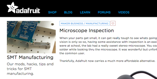
Adafruit has a great set of tutorials for handling SMD parts, but they're aimed at manufacturers rather than prototypers. Also we do things a little differently here, but still worth a read for if you end up doing small-scale manufacturing in the future.
Using the Pick-and-Place Machine
Production #4
This machine is not useful until you are populating at least 20-100 boards in one day. I have a hard time believing that will ever happen during an ITP semester.
Programming Jigs
Production #5
- Here's a tutorial on making a "real" programming jig. This is too professional for what we'll be doing in class, but you can imagine how much design goes into just thinking about how something will be programmed.
- Here's an example of someone hot-gluing some wire to program a dead Pro Mini. That's a jig too.
Bootloaders
Production #5
A Bootloader is a small piece of code that we usually need to put on our microcontrollers before we can program them with Arduino. Any board that works with the Arduino IDE has an "Arduino" bootloader inside it, giving it the ability to load code from the Arduino IDE.
Here's an explanation of what the Arduino Bootloader is from Sparkfun.
Whenever code is transfered from a computer to a microcontroller, something must be in the middle acting as a converter. This is a usb-to-serial converter, or a usb-to-spi converter, or something similar. These middle devices are call In-System Programmers (ISP).
Here's a tutorial on using Arduino as an ISP (In System Programmer)
Here's an example of adding a bootloader to an nRF51822, so that we can program it with Arduino. Unlike Atmel chips which use the mkii as an ISP, the nRF5x chips use the J-Link as an ISP.